www.ams.com/AS5013
Revision 1.11
13 - 32
AS5013
Datasheet - Detailed Description
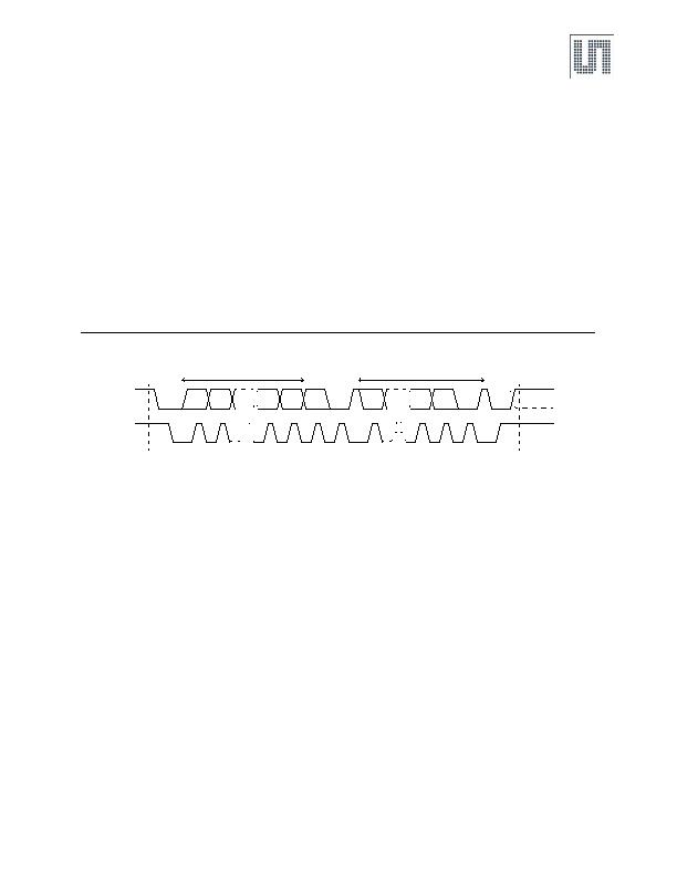
Bus Not Busy: Both data and clock lines remain HIGH.
Start Data Transfer: A change in the state of the data line, from HIGH to LOW, while the clock is HIGH, defines a START condition.
Stop Data Transfer: A change in the state of the data line, from LOW to HIGH, while the clock line is HIGH, defines the STOP condition.
Data Valid: The state of the data line represents valid data when, after a START condition, the data line is stable for the duration of the HIGH
period of the clock signal. The data on the line must be changed during the LOW period of the clock signal. There is one clock pulse per bit of
data. Each data transfer is initiated with a START condition and terminated with a STOP condition. The number of data bytes transferred
between START and STOP conditions are not limited, and are determined by the master device. The information is transferred byte-wise and
each receiver acknowledges with a ninth bit.
Acknowledge: Each receiving device, when addressed, is obliged to generate an acknowledge after the reception of each byte. The master
device must generate an extra clock pulse that is associated with this acknowledge bit.
A device that acknowledges must pull down the SDA line during the acknowledge clock pulse in such a way that the SDA line is stable LOW
during the HIGH period of the acknowledge-related clock pulse. Of course, setup and hold times must be taken into account. A master must
signal an end of READ access to the slave by not generating an acknowledge bit on the last byte that has been clocked out of the slave. In this
case, the slave must leave the data line HIGH to enable the master to generate the STOP condition.
Figure 10. Data Read (Write Pointer, Then Read) - Slave Receive and Transmit
Depending upon the state of the R/W bit, two types of data transfer are possible:
n Data transfer from a master transmitter to a slave receiver: The first byte transmitted by the master is the slave address, followed by R/
W = 0. Next follows a number of data bytes. The slave returns an acknowledge bit after each received byte. If the slave does not understand
the command or data it sends a
not acknowledge
. Data is transferred with the most significant bit (MSB) first.
n Data transfer from a slave transmitter to a master receiver: The master transmits the first byte (the slave address). The slave then
returns an acknowledge bit, followed by the slave transmitting a number of data bytes. The master returns an acknowledge bit after all
received bytes other than the last byte. At the end of the last received byte, a
not acknowledge
is returned. The master device generates
all of the serial clock pulses and the START and STOP conditions. A transfer is ended with a STOP condition or with a repeated START
condition. Since a repeated START condition is also the beginning of the next serial transfer, the bus is not released. Data is transferred with
the most significant bit (MSB) first.
The AS5013 can operate in the following two modes:
n Slave Receiver Mode (Write Mode): Serial data and clock are received through SDA and SCL. Each byte is followed by an acknowledge
bit (or by a not acknowledge depending on the address-pointer pointing to a valid position). START and STOP conditions are recognized as
the beginning and end of a serial transfer. Address recognition is performed by hardware after reception of the slave address and direction
bit (see Figure 11). The slave address byte is the first byte received after the START condition. The slave address byte contains the 7-bit
AS5013 address, which is stored in the OTP memory.
The 7-bit slave address is followed by the direction bit (R/W), which, for a write, is 0. After receiving and decoding the slave address byte the
device outputs an acknowledge on the SDA. After the AS5013 acknowledges the slave address + write bit, the master transmits a register
address to the AS5013. This sets the address pointer on the AS5013. If the address is a valid readable address the AS5013 answers by
sending an acknowledge. If the address-pointer points to an invalid position a
not acknowledge
is sent. The master may then transmit zero
or more bytes of data. In case of the address pointer pointing to an invalid address the received data are not stored. The address pointer will
increment after each byte transferred independent from the address being valid. If the address-pointer reaches a valid position again, the
AS5013 answers with an acknowledge and stores the data. The master generates a STOP condition to terminate the data write.
1
1
9
8
7
6
2
9
8
7
DA
CL
Start
Condition
Stop Condition or
Re eated Start Condition
MSB
R/W ACK
LSB
ACK
Slave Address
Repeated if more Bytes are transferred
发布紧急采购,3分钟左右您将得到回复。
相关PDF资料
AS5115-HSST-500
IC ENCODER ROTARY 16-SSOP
AS5130-ASST-500
IC ENCODER ROTORY 8-BIT 16-SSOP
AS5132-HSST-500
IC ENCODER ROTARY 20-SSOP
AS5134-ZSST-500
IC ENCODER RPTARY 20-SSOP
AS5140H-ASST
IC ENCODER ROTARY 10BIT 16-SSOP
AS5145B-HSST-500
IC ENCODER ROTARY MAGN 16-SSOP
AS5510-DWLT
IC ENCODER MAGNETIC LIN 6-WLCSP
ATS137-PL-B-B
IC HALL SENSOR SGL 25MA SIP-3L
相关代理商/技术参数
AS5013-IQFT-6000
制造商:AMS 功能描述:IC ENCODER HALL SENSOR 16-QFN
AS5013-QF_EK_AB
功能描述:AS5013 ADAPTER BOARD 制造商:ams 系列:- 零件状态:在售 传感器类型:霍尔效应 感应范围:- 接口:I2C 灵敏度:- 电压 - 电源:2.7 V ~ 3.6 V 嵌入式:- 所含物品:板 使用的 IC/零件:AS5013 标准包装:1
AS5013-QF_EK_DB
功能描述:AS5013, N40P112 EasyPoint? Series Interface, Hall Effect Sensor Human Interface Device (HID) Evaluation Board 制造商:ams 系列:EasyPoint?? 零件状态:过期 主要用途:接口,霍尔效应传感器人机界面设备(HID) 嵌入式:否 使用的 IC/零件:AS5013,N40P112 主要属性:模拟操纵杆,带 3 个按钮 辅助属性:USB 接口 所含物品:板,线缆 标准包装:1
AS50-150K-RC
制造商:ALLIED 制造商全称:Allied Components International 功能描述:Axial Shielded Inductors
AS50-151K-RC
制造商:ALLIED 制造商全称:Allied Components International 功能描述:Axial Shielded Inductors
AS50-152K-RC
制造商:ALLIED 制造商全称:Allied Components International 功能描述:Axial Shielded Inductors
AS50-153K-RC
制造商:ALLIED 制造商全称:Allied Components International 功能描述:Axial Shielded Inductors
AS50-180K-RC
制造商:ALLIED 制造商全称:Allied Components International 功能描述:Axial Shielded Inductors